Making Stainless Steel Cylinder Flange Nuts
I had already made and fitted scale nuts for the cylinder flange – holding the cylinder to the boiler.
Some had become a bit rusty and dirty but all of them appeared dirty because I had coated them with an ‘invisible’ anti-rust spray. This had tarnished and made the nuts look like they were rusty and dirty.
So I decided to remake the nuts from stainless steel.
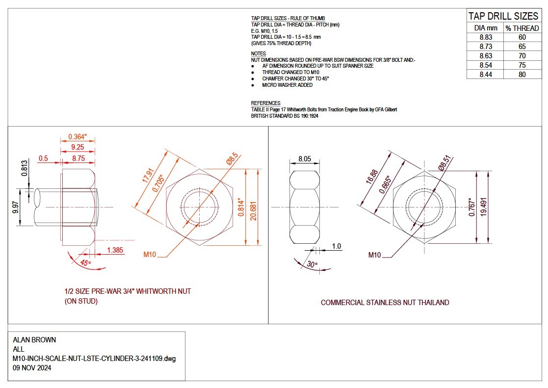
The threads nuts on the full size traction engine were 3/4″ diameter with Whitworth thread form. The scale nuts being half size would therefore be 3/8″ thread. I made the threads M10, (10mm diameter) being very close to 3/8″.
Gallery Showing How I Made Stainless Steel Nuts to 6″/ft Scale (M10 Thread)
12 Stainless Steel Cylinder Stud Nuts Finished CloseUp
More Details of Making M10 Scale Stainless Steel Nuts
Here is a commentary showing how I made the nuts, starting with my CAD drawing.
CAD Drawing of 1/2 Sized Scale 3/4 Inch Pre-War Nuts
Click on the image to see a larger photo, click on the arrow to see the next image.
Photos of the Finished Stainless Steel Nuts
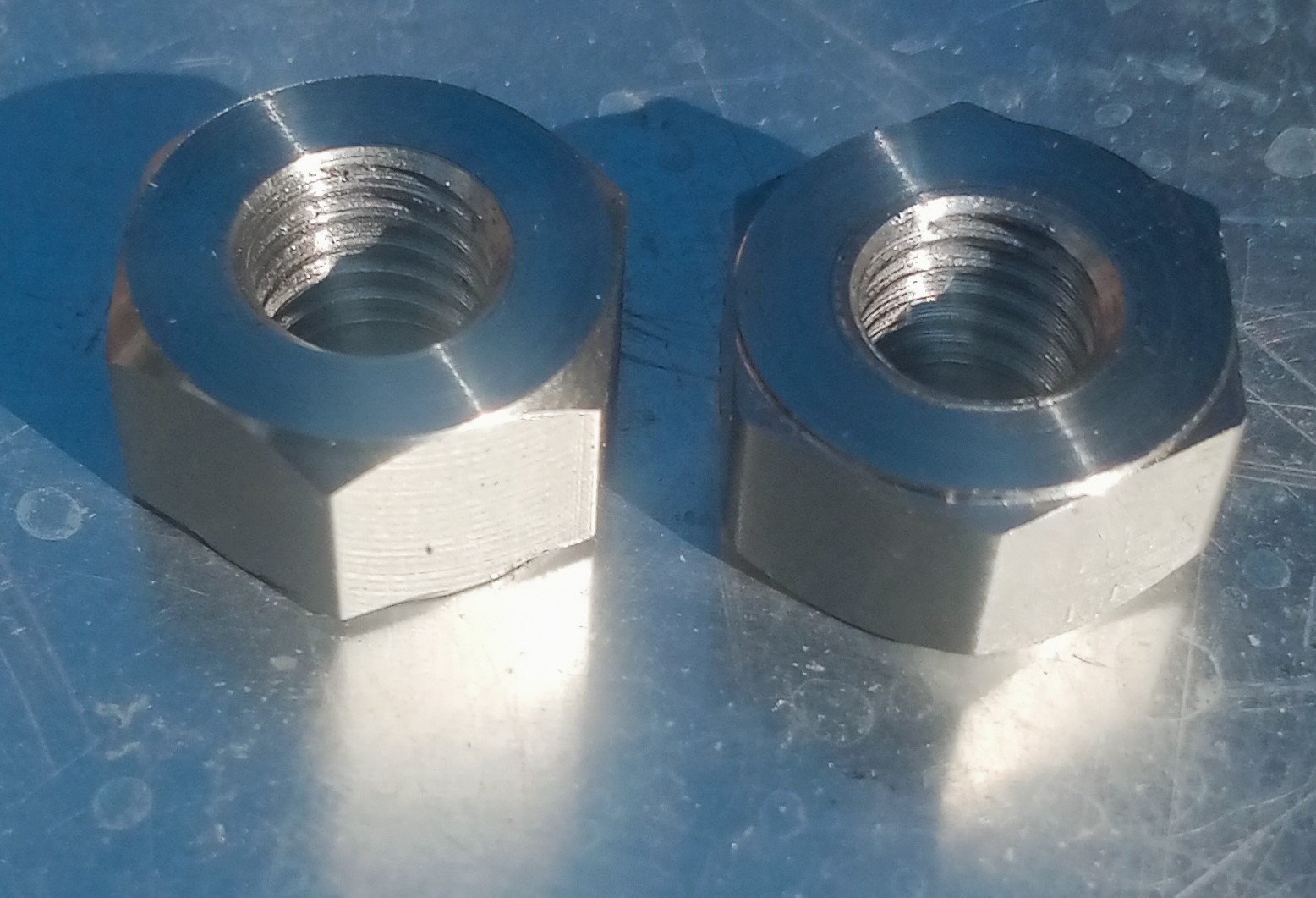
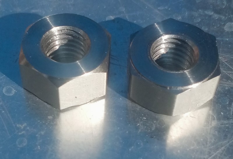
Here is a close up of two of the finished stainless steel cylinder flange nuts:-
The photo on the left clearly shows the 45 degree chamfer (explanation below) and the photo on the right shows the micro washer on the underside of the nut.
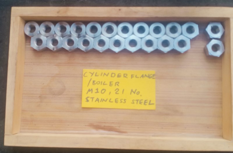
Here is a photo of the complete set of finished cylinder flange nut for the 6″ scale Little Samson Traction Engine:-
21 Nuts in total plus two spare.
Mill Setup for Machining Hex Bar
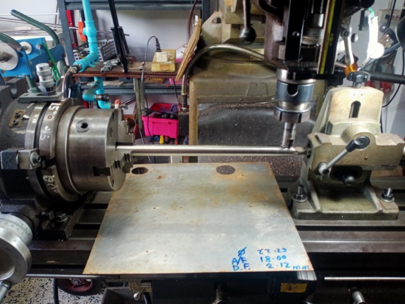
This is a photo showing the setup on the vertical milling machine to turn (mill!) round stainless steel bar into hexagonal stock for the production of the stainless steel cylinder saddle nuts:-
You can see written on the aluminium swarf guard that the round bar diameter is 22.23 mm (7/8″) and the desired across flats (AF) dimension is 18mm, to fit an 18mm spanner. Also shown is the total depth of cut for each flat – 2.12 mm.
The bar is about 420 mm long and the finished length of the hex portion is about 317 mm, enough for 21 nuts.
The bar is held at one end by a Vertex Rotary Table and supported at the outer end by a tailstock. I had previously modified the rotary table to allow spin indexing and you can see the indexing indent at the top. A great timesaver.
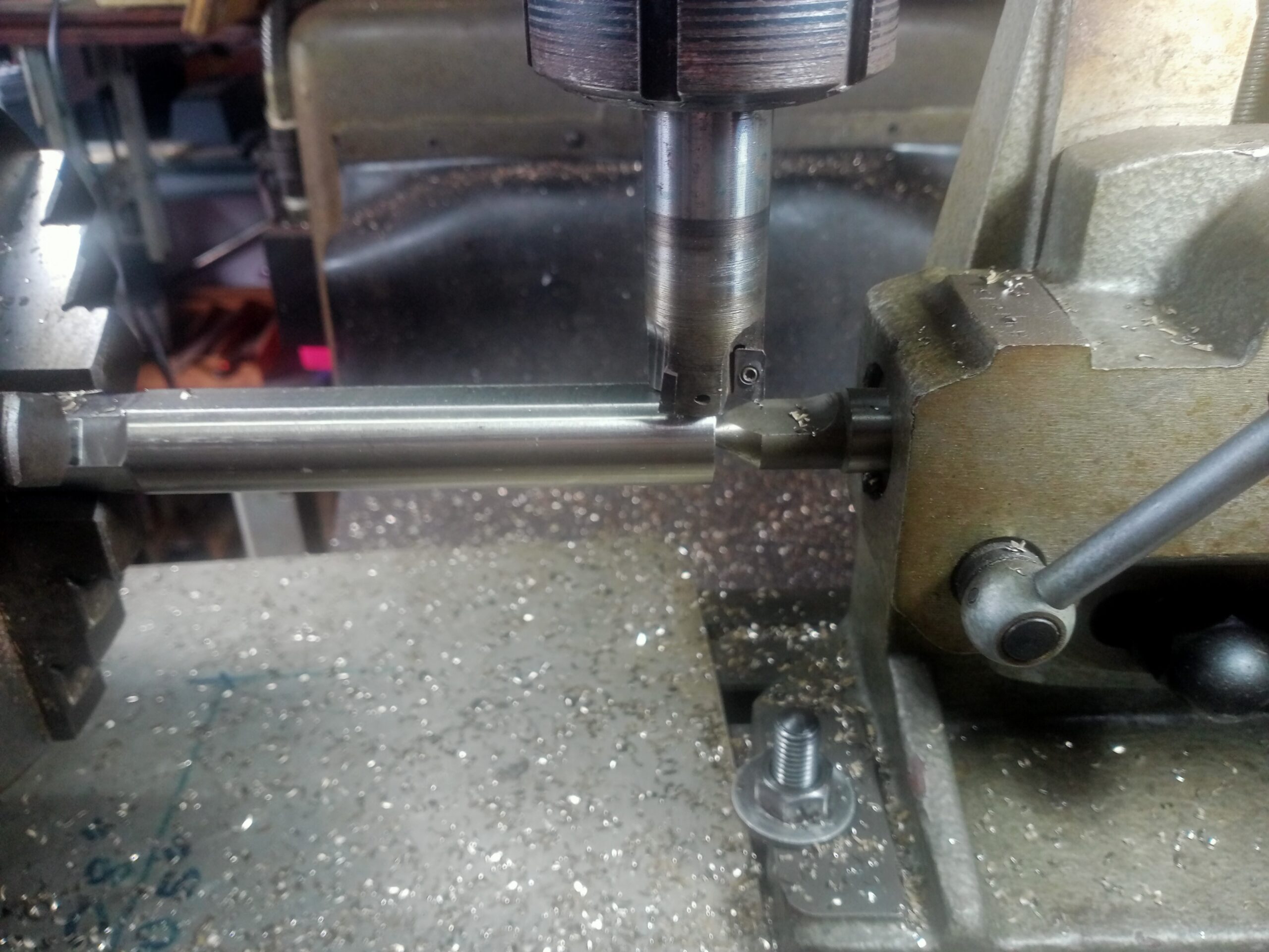
The next photo is a close-up of the milling cutter.
The cutter holder is 25mm diameter and holds three Mitsubishi APMT 1135 PDER carbide inserts. These are great inserts for light machines because they have a positive top rake. Running at the lowest direct drive of the mill spindle, 600 rpm, a depth of cut of 0.4mm was taken, meaning 6 cuts per flat with minimal (acceptable) chatter even on this long length of unsupported bar.
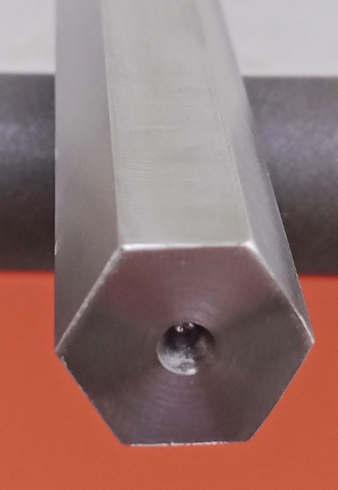
The Hexagon Bar Ready for Machining the Nuts
Below is a photo of the hexagon bar ready to start machining the individual nuts.
Stainless Steel Cylinder Stud Nuts Tapping Setup
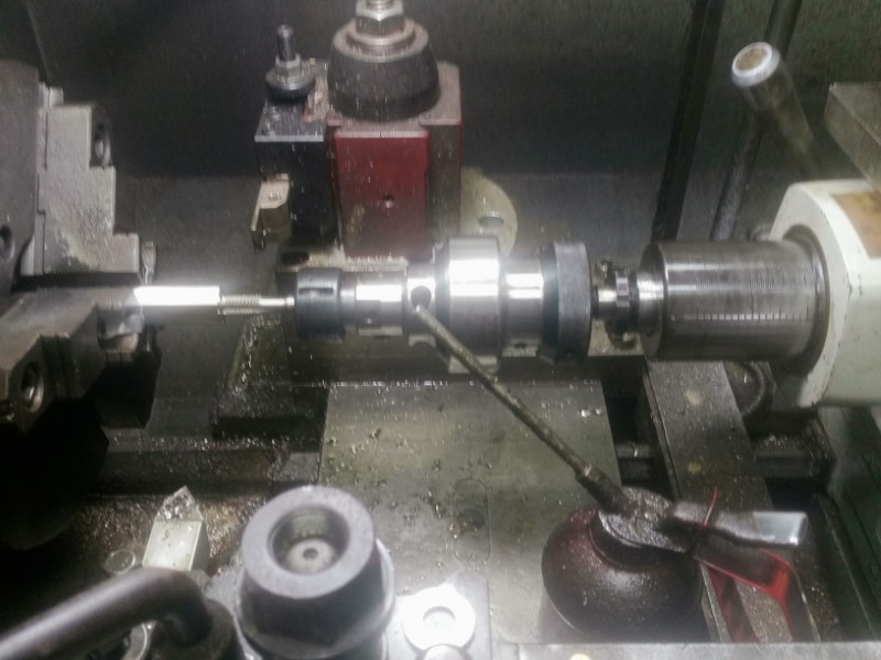
This is the setup on the lathe for machining and tapping the scale nuts from the pre-machined hexagon bar stock:-
The photo above shows the bar stock undergoing tapping after being drilled tapping size. Following tapping, the bar stock is chamfered and the parting tool in the rear backpost is used to form the micro washer after which the nut is parted off.
The drilling and tapping tools are only long enough to thread the hexagon bar stock deep enough to make two nuts at a time.
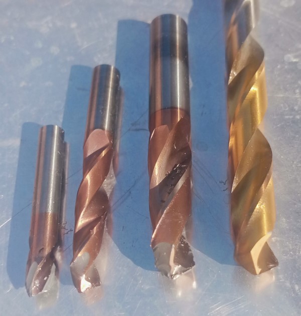
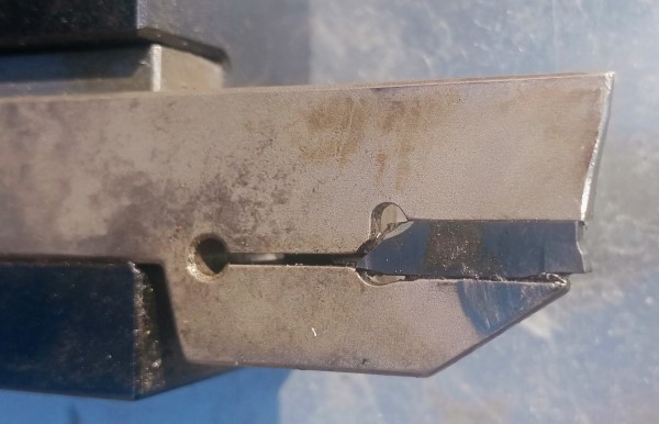
Drilling the stainless steel bar was difficult and several drills both carbide and high speed steel (HSS) were destroyed as shown below. Also the rear parting tool gave up on the last two nuts.
Strangely, the tapping process was straightforward. A normal HSS taper tap was used first, mounted in the special tap holder in the tailstock, Then a finish spiral tap was used in a hand-held tap-wrench to finish the thread to full depth. Special treading cutting oil was applied from the oil can.
After all the nuts had been tapped, chamfered and parted off, they underwent a second process of deburring the underside of the nuts as shown in the photos below.
Stainless Steel Cylinder Stud Nuts Deburring Process
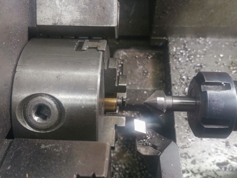
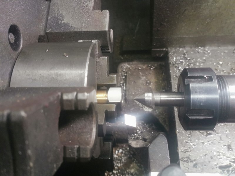
The first photo shows the setup for mounting the nuts for deburring. A general-purpose chuck backstop I had previously made was mounted in the bore of the chuck. This provided an M10 threaded rod onto which the nut was screwed and seated on the brass collar.
Then the chuck jaws were closed onto the faces of the nut and the countersink tool in the tailstock chuck used to deburr the nut, as shown below:-
Tool Wear
The photos below show the tools that were destroyed in the process of machining the nuts from the hex stainless steel bar.
The first photo shows the drills that were destroyed.
Selection of HSS and Carbide Drills Destroyed Machining the Nuts
The Parting-Off Tool and Carbide Insert Destroyed Machining the Nuts
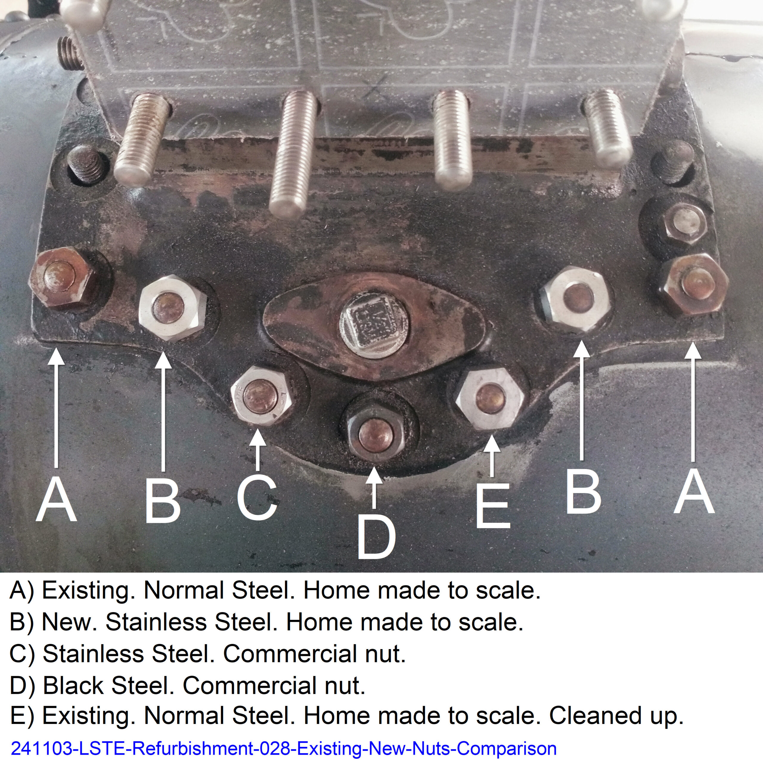
Comparison of Existing and New Nuts
Here is a photo comparing the existing nuts (A) and ditto cleaned up (E) with the new stainless steel nuts (B) and two commercial nuts.
Note that the studs do not excessively protrude beyond the top of the nuts. Ideally I aim to have one full thread above the nut – no more.
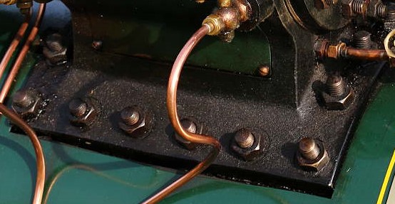
Cylinder Flange Nuts Excessive Stud Length Example
This next photo exemplifies my pet hate with models of engines – all types. And that is use of commercial nuts and studs that stick out way above the top of the nut. Horrible; and to me this destroys all the hard work the builder has put into building the remainder of the engine very nicely and to prototype.
Additional Features of the New Nuts
At the same time I added the following features to the nuts:-
45 Degree Chamfer.
The ‘standard’ chamfer on nuts is 30 degrees. But this is not very prominent and difficult to see. So for purely visual reasons I decided to increase the 30 degree chamfer to 45 degrees. Do you think the look better?
Hidden Micro Washers
Unlike modern machine assemblies, back in the early 1900’s when these Little Samson Traction Engines were being built they didn’t use washers under nuts. I originally followed this principle to be authentic to prototype but the result was that the corners of the nuts scrapped off the paint from the cylinder flanges as the nuts were tightened.
So I machined ‘invisible’ micro-washer 0.5 mm thick into the base of the nuts. Now the corners of the nuts don’t scrape the paint away but the washers are not visible thereby keeping the original authentic prototype appearance.
