Little Samson Traction Engine Final Machining of Front Wheel Assembly
– The Procedure and The Logic Behind It
Published 8 December 2014
Introduction
Two front wheels are in process of being built. One has all the spokes in place and turns with 1 mm axial run-out. This is called the First Wheel.
The second wheel does not have all the spokes and I am not happy with it for reasons to be explained elsewhere. It was originally planned to progress construction of both wheels simultaneously but it has now been decided to complete the first wheel 100% and then move back to completing the second wheel.
Many thoughts have been running through my mind as to the best way to finish off the front wheels and have something to show for all the time and effort I have expended on building the Little Samson to date.
My mind keeps running through logical arguments and procedures sometimes over and over again and often when I am asleep! It’s time to get all these thoughts out of my head and on to paper to stop this incessant chattering to clear my head and so that I will be able to test the logic and fill in any missing gaps.
A movie and photos and of the first front wheel can be seen here:-
A Video Of The Front Wheels Half Spoked-up Spinning On The Wheel Building Jig
Photos Of The Front Wheel With All Spokes In Place
Requirements and Constraints
Spokes
Spoke fixing at the Hub is by 1 X 8mm countersunk hexagon head socket screw per spoke and by the close fit of the hub spoke in the hub slot. Fixing will be improved further by the Hub Cover Plates and by adhesive on final assembly.
Some people add a hardened steel pin to each spoke, others cut the spoke slots to a dead end and fit the spokes to abut against it.
I intend to take an easier route and machine the hub bore and spoke ends at one setting to suit the Axle Bearing OD so that the ends of the spokes bear on the OD of the axle bearing.
Sketch 1.
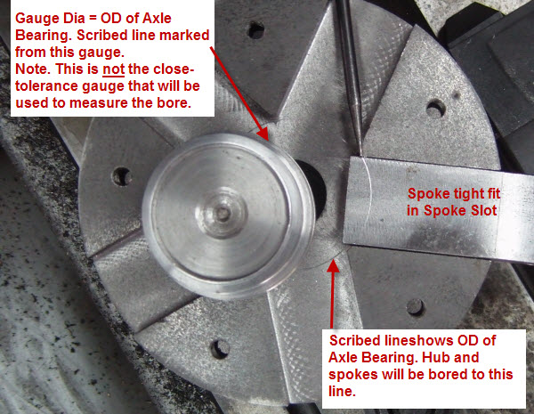
Front Wheel Hub & Spoke Showing Axle Bearing Size
Axle Bearings
The Drawings
By “The Drawings” am referring to the construction drawings purchased from Little Samson Models. This clarification is necessary because I also produce my own drawings to expand on and clarify the intent of The Drawings. Similarly “The Design” means the design as depicted by The Drawings, because I am departing from it in some minor details.
The Drawings show a single (per wheel) straight bearing sleeve for the Axle.
The axle journal and the wheel retaining collar both bear on the bearing ends hence any axial force on the wheel in either direction will tend to push the bearing axially through the hub. There is no positive means to locate the axle bearing laterally other than the friction fit between the bearing OD and the hub ID.
This must therefore be made an interference fit.
The bearing is intended to be a replaceable item when worn and an interference fit will make replacement difficult.
I have poured over the book “Traction Engine Design and Construction 1900 – 1930” by G.F.A Gilbert to try to find out how the bearings were retained on full sized engines. All the drawings I have studied in the book show a positive location for the bearings by, for example, a taper, flanges, or screwed fixings.
My Design
I will split each bearing into two, each with a locating flange on the outer end they will be a light press fit in the hub. A 1/4″ gap between the two bearing halves will provide a lubricant reservoir.
This will impose a constraint in that each bearing half will have to be pressed into the hub separately and from opposite sides of the hub.
Sketch 2.
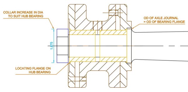
Sketch of Front Hub Axle Assembly With Flanged Axle Bearing
If the hub bore is being machined in the lathe it will not be possible to insert the bearing and finish-bore the bearing bore in situ. (Sometimes recommended to achieve a true-running wheel)
In any case, since the bearings are intended to be replaceable then:-
- The OD and ID must be concentric and parallel. (Not necessarily the case if the bore is finished in situ in the hub)
- The bearings and hub bores must be dimensionally identical to defined tolerances.
This means that:-
- The hub bores should be finished bored at the same lathe tool setting.
- The bearing OD and ID should similarly be finish machined at the same lathe tool setting.
The procedure for machining the bearings is as Sketch 3.
Sketch 3.
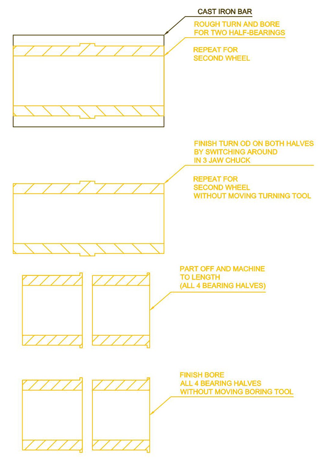
Front Hub Axle Bearing Machining Sequence
Close-tolerance plug gauges have been made to facilitate machining bores to a tolerance. This also allows replacement bearings to be made easily to fixed dimensions.
Hub Bores
In order to allow finishing boring of hubs with the same lathe tools setting each hub must be finish-bored in sequence in the lathe.
But the intention now is to finish one wheel completely before competing the second wheel so this can no longer be followed.
However, by using the close-tolerance plug gauges, it should be feasible to machine each hub separately to adequate accuracy and this is what i plan to do.
Hub/Spoke/Wheel Assembly
As mentioned above, the first wheel has an axial run-out of 1 mm (40 thou) at the wheel rim.
Sketch 4.
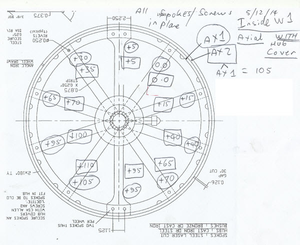
Front Wheel Spin Test Results Front Wheel 1-2
Whilst this is quite small it is desired to eliminate it completely.
It is desired to machine the hub bore with the spokes and hub covers in situ at one setting in the lathe to allow:-
- Identical and concentric bores in hub and hub covers.
- Inner ends of spokes to be a close fit in the axle bearing OD.
To do this machining the hub could be held in the 3 jaw chuck by the hub cover but there would be insufficient grip for this to be safe. The 3 jaw chuck jaws will not fit between the spokes to grip the hub proper.
The hub will therefore have to be machined by mounting it on the faceplate. The procedure is to set up and secure the hub complete with spokes, hub covers and wheel rim to the faceplate using the mill table and the quill to ensure concentricity.
The hub can be packed up on one side to eliminate the run-out.
Note that:-
- The faceplate (purchased recently for this specific purpose) has never been mounted on the lathe spindle. This needs testing as a preliminary exercise. The cause for doubt is that the lathe spindle nose is equipped with a D1-6 Camlock to attach chucks. The faceplate has no Camlock but has holes for cap screws. I’m not sure about the compatibility of these two different securing systems.
- The lathe bed gap will have to be removed. Again this is something I have never attempted before.
Other Operations and Final Assembly and Painting
There are several other operations to be completed:-
- Fit the dummy rivets for the tyre.
- Drill and tap the hub for the oiler. *
- Cut tyres diagonally. *
- Round off the hub covers, turn recesses for axle journal, axle securing collar and hub cap.
- Replace all bolts by rivets.
- Completely clean, fill as necessary and prepare for painting then paint all surfaces. At least two coats of primer. Pay particular attention to the flange/rim fillet welds which will need body filler. (All this must be done before re-assembly). *
- Develop riveting procedure on separate components. This will need:-
- Rivet Sets
- Rivet Dolly
- Big Hammer
- Ear Defenders!
- Rivet Cutter (Cut to length)
- Hydraulic Press – Experiment
* items need the complete strip down of the bub spokes and rim.
The following sequence is proposed:-
- Machine axle bearings (for two wheels)
- Machine round edged profile and recesses on hub covers.
- Test faceplate fit on the lathe.
- Completely strip the wheel, marking each piece and it’s mate with centre dot marks.
- Fit dummy tyre rivets.
- Cut tyres diagonally.
- Drill and tap hub for oiler.
- Rough bore hub together with cover plates to final ID to suit the axle bearings OD less a generous allowance for final machining on the finished assembly. Similarly, cut back the inner ends of the spokes to reduce machining on final assembly.
- Completely clean all items and paint as described above.
- Re-assemble using bolts.
- Develop riveting procedure as above.
- Replace bolts with rivets.
- Finish bore hub on faceplate.
- Press in axle bearings.
Note. It has been decided to bore the hubs after riveting as riveting may cause rim movement.
Rough Time Estimate
I expect the above to take not less than a month of time.
Other Works and Ancillaries
As an afterthought the following items are required before the wheel can be considered 100% complete:-
- Final colour painting and lining.
- Make oiler caps.
Need to re-make the broken 1/2″ x 32 ME Tap.
Need to test and confirm the knurling machine. - During machining the hubs, the tyres will be cleaned up using carbide paper and sprayed with clear acrylic paint.
- During assembly of the spokes and hub covers a suitable adhesive and filler will be applied. Needs to be thin because the gaps are very small and also very strong.
Final Thoughts
This is a Plan.
The Plan needs to be under constant review and re-assessment as works proceed.